 Wenzhou Kaixin Kaixin Metal Co.,LTD

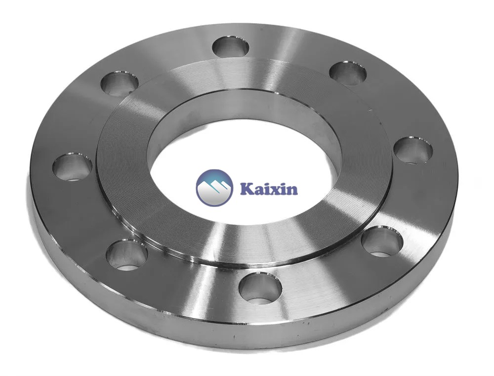
What is Stainless Steel Slip on flange used and dimensions?
A stainless steel slip-on flange, also known as a SO flange, is a type of flange that is easily slipped on and off a pipe or fitting. It is designed to slide over the end of the pipe or fitting and be welded in place. The flange has a flat face for the connection and is secured to the pipe or fitting with bolts. The slip-on flange is commonly used for low-pressure applications and is available in various sizes and materials, including stainless steel, carbon steel, and alloy steel. The benefits of using a stainless steel slip-on flange include its durability, corrosion resistance, and ease of installation.
Table of Content:
- Slip-On Flanges Specification
- Applicationsof Slip-On Flanges
- Types of Slip On Flange Welding.
- Referred Standard and Grades
- Advantages of Slip On Flange
- Slip-on flange datasheets
- Slip on Flange Dimensions – Class 150 to Class 1500
Slip-On Flanges Specification
Material: Carbon, Alloy and Stainless Steel
Standards: ASTM A105, ASTM A182
Sizes: 1/2” to 24”, Customized up to 48”
Thickness: Schedule 10(S) to SCH 160
Pressure Ratings: Class 150, Class 300, 400, 600, 900, 1500, 2500(# or LB). PN 2.5 to PN 250
Flange face type: RF (Raised Face), RTJ (Ring Type Joint)
Applications of Slip-On Flanges
They are mainly used for fluids at low pressure or with little risk of leakage. It is very common to find these flanges today in cooling water lines, firefighting water lines, low-pressure compressed air lines, and process lines for substances such as steam, oil, gas, condensates, etc.
Types Of Slip On Flange Welding.
The SO flange can be divided into SO welding plate flange and SO welding hubbed steel pipe flange. Its mechanical characteristics are between the integral flange and the looping flange. The structure is simple, and the processing is convenient. So slip on flange welding is widely used in various fluid pipelines.
Depends on different face, there are also ranges raised face type and ring type joint face type.
- Raised Face Slip On Flange
There is a small portion extruded from the bottom face of the slip on flange, this type is raised face slip on flange. The function of this area is to place a gasket seat during installation to get a better sealing performance.
As the pressure ratings bigger, the height of this raised face will be bigger.

Stainless Steel Slip on flange 10inch dimension drawing
- RTJ Slip on Flange
A small grooved is machined on the raised face part, this form is called RTJ type, the function of this groove is to place the gasket ring, also applied for sealing, compared to RF type, RTJ is designed for high pressure use.

Stainless Steel Slip on flange 10inch rtj dimension drawing
Slip on flange use slip welding to connect equipment, so either below of name is describing the same flange:.
- Slip on weld flange
- Slip on flange weld
- Weld slip on flange
- Slip on flange welding
- SO flange
Referred Standard and Grades
ASTM A105 for carbon steel slip on pipe flanges.
ASTM A182 for alloy and stainless slip on flanges. (Alloy for F11, F22, stainless for F304/F304L, F316/F316L)
ASME B16.5 for pipe flanges and flanged fittings.
BS 3293
DIN 86029
Advantages of Slip On Flange
- Installation costs are lower
- Less time is spent on accurately cutting the pipe
- Easier alignment
- Low hub on slip-on flanges due to pipe slips in the flange
- Interior and outer welding of flange
- Leak prevention
Slip-on flange datasheets
For simplicity sake, only datasheets that adhere to B16.5 are shown. ASME B16.5 covers flange dimensions from ½” to 24”.
| Class | Flat Face | Raised Face | Ring Type Joint |
| ANSI 150 | SO Flange ANSI 150 FF (in) | SO Flange ANSI 150 RF (in) | SO Flange ANSI 150 RTJ (in) |
| ANSI 300 | SO Flange ANSI 300 FF (in) | SO Flange ANSI 300 RF (in) | SO Flange ANSI 300 RTJ (in) |
| ANSI 400 | SO Flange ANSI 400 FF (in) | SO Flange ANSI 400 RF (in) | SO Flange ANSI 400 RTJ (in) |
| ANSI 600 | SO Flange ANSI 600 FF (in) | SO Flange ANSI 600 RF (in) | SO Flange ANSI 600 RTJ (in) |
| ANSI 900 | SO Flange ANSI 900 FF (in) | SO Flange ANSI 900 RF (in) | SO Flange ANSI 900 RTJ (in) |
| ANSI 1500 | SO Flange ANSI 1500 FF (in) | SO Flange ANSI 1500 RF (in) | SO Flange ANSI 1500 RTJ (in) |
| ANSI 2500 | SO Flange ANSI 2500 FF (in) | SO Flange ANSI 2500 RF (in) | SO Flange ANSI 2500 RTJ (in) |
Slip on Flange Dimensions – Class 150 to Class 1500
Slip on flange dimensions are covered in ASME B16.5 – which covers Pipe Flanges and Flanged Fittings for size NPS ½” to 24” for above NPS 26” to 60” it should be as per ASME B16.47.
During a dimensional inspection of slip on flange, you should check for
- Outer & Inner Diameter of body
- Bolt Circle & Bolt Hole Diameter
- Length of the Hub
- Straightness and alignment of the bolt hole

Stainless Steel Slip on flange dimension drawing
Class 150 Slip-on Flange Dimensions
| Size in Inch | Size in mm | Outer Dia. | Flange Thick. | Hub OD | Flange Length | RF Dia. | RF Height | PCD | Socket Bore | No of Bolts | Bolt Size UNC | Machine Bolt Length | RF Stud Length | Hole Size | ISO Stud Size | Weight in kg |
| A | B | C | D | E | F | G | H | |||||||||
| 1/2 | 15 | 90 | 9.6 | 30 | 14 | 34.9 | 2 | 60.3 | 22.2 | 4 | 1/2 | 50 | 55 | 5/8 | M14 | 0.8 |
| 3/4 | 20 | 100 | 11.2 | 38 | 14 | 42.9 | 2 | 69.9 | 27.7 | 4 | 1/2 | 50 | 65 | 5/8 | M14 | 0.9 |
| 1 | 25 | 110 | 12.7 | 49 | 16 | 50.8 | 2 | 79.4 | 34.5 | 4 | 1/2 | 55 | 65 | 5/8 | M14 | 0.9 |
| 1 1/4 | 32 | 115 | 14.3 | 59 | 19 | 63.5 | 2 | 88.9 | 43.2 | 4 | 1/2 | 55 | 70 | 5/8 | M14 | 1.4 |
| 1 1/2 | 40 | 125 | 15.9 | 65 | 21 | 73 | 2 | 98.4 | 49.5 | 4 | 1/2 | 65 | 70 | 5/8 | M14 | 1.4 |
| 2 | 50 | 150 | 17.5 | 78 | 24 | 92.1 | 2 | 120.7 | 61.9 | 4 | 5/8 | 70 | 85 | 3/4 | M16 | 2.3 |
| 2 1/2 | 65 | 180 | 20.7 | 90 | 27 | 104.8 | 2 | 139.7 | 74.6 | 4 | 5/8 | 75 | 90 | 3/4 | M16 | 3.2 |
| 3 | 80 | 190 | 22.3 | 108 | 29 | 127 | 2 | 152.4 | 90.7 | 4 | 5/8 | 75 | 90 | 3/4 | M16 | 3.7 |
| 3 1/2 | 90 | 215 | 22.3 | 122 | 30 | 139.7 | 2 | 177.8 | 103.4 | 8 | 5/8 | 75 | 90 | 3/4 | M16 | 5 |
| 4 | 100 | 230 | 22.3 | 135 | 32 | 157.2 | 2 | 190.5 | 116.1 | 8 | 5/8 | 75 | 90 | 3/4 | M16 | 5.9 |
| 5 | 125 | 255 | 22.3 | 164 | 35 | 185.7 | 2 | 215.9 | 143.8 | 8 | 3/4 | 85 | 95 | 7/8 | M20 | 6.8 |
| 6 | 150 | 280 | 23.9 | 192 | 38 | 215.9 | 2 | 241.3 | 170.7 | 8 | 3/4 | 85 | 100 | 7/8 | M20 | 8.6 |
| 8 | 200 | 345 | 27 | 246 | 43 | 269.9 | 2 | 298.5 | 221.5 | 8 | 3/4 | 90 | 110 | 7/8 | M20 | 13.7 |
| 10 | 250 | 405 | 28.6 | 305 | 48 | 323.8 | 2 | 362 | 276.2 | 12 | 7/8 | 100 | 115 | 1 | M24 | 19.5 |
| 12 | 300 | 485 | 30.2 | 365 | 54 | 381 | 2 | 431.8 | 327 | 12 | 7/8 | 100 | 120 | 1 | M24 | 29 |
| 14 | 350 | 535 | 33.4 | 400 | 56 | 412.8 | 2 | 476.3 | 359.2 | 12 | 1 | 115 | 135 | 1 1/8 | M27 | 41 |
| 16 | 400 | 595 | 35 | 457 | 62 | 469.9 | 2 | 539.8 | 410.5 | 16 | 1 | 115 | 135 | 1 1/8 | M27 | 54 |
| 18 | 450 | 635 | 38.1 | 505 | 67 | 533.4 | 2 | 577.9 | 461.8 | 16 | 1 1/8 | 125 | 145 | 1 1/4 | M30 | 59 |
| 20 | 500 | 700 | 41.3 | 559 | 71 | 584.2 | 2 | 635 | 513.1 | 20 | 1 1/8 | 140 | 160 | 1 1/4 | M30 | 75 |
| 24 | 600 | 815 | 46.1 | 663 | 81 | 692.2 | 2 | 749.3 | 616 | 20 | 1 1/4 | 150 | 170 | 1 3/8 | M33 | 100 |
Class 300 Slip-on Flange Dimensions
| Size in Inch | Size in mm | Outer Dia. | Flange Thick. | Hub OD | Flange Length | RF Dia. | RF Height | PCD | Socket Bore | No of Bolts | Bolt Size UNC | Machine Bolt Length | RF Stud Length | Hole Size | ISO Stud Size | Weight in kg |
| A | B | C | D | E | F | G | H | |||||||||
| 1/2 | 15 | 95 | 12.7 | 38 | 21 | 34.9 | 2 | 66.7 | 22.2 | 4 | 1/2 | 55 | 65 | 5/8 | M14 | 1.2 |
| 3/4 | 20 | 115 | 14.3 | 48 | 24 | 42.9 | 2 | 82.6 | 27.7 | 4 | 5/8 | 65 | 75 | 3/4 | M16 | 1.4 |
| 1 | 25 | 125 | 15.9 | 54 | 25 | 50.8 | 2 | 88.9 | 34.5 | 4 | 5/8 | 65 | 75 | 3/4 | M16 | 1.4 |
| 1 1/4 | 32 | 135 | 17.5 | 64 | 25 | 63.5 | 2 | 98.4 | 43.2 | 4 | 5/8 | 70 | 85 | 3/4 | M16 | 1.8 |
| 1 1/2 | 40 | 155 | 19.1 | 70 | 29 | 73 | 2 | 114.3 | 49.5 | 4 | 3/4 | 75 | 90 | 7/8 | M20 | 2.7 |
| 2 | 50 | 165 | 20.7 | 84 | 32 | 92.1 | 2 | 127 | 61.9 | 8 | 5/8 | 75 | 90 | 3/4 | M16 | 3.2 |
| 2 1/2 | 65 | 190 | 23.9 | 100 | 37 | 104.8 | 2 | 149.2 | 74.6 | 8 | 3/4 | 85 | 100 | 7/8 | M20 | 4.6 |
| 3 | 80 | 210 | 27 | 117 | 41 | 127 | 2 | 168.3 | 90.7 | 8 | 3/4 | 90 | 110 | 7/8 | M20 | 5.9 |
| 3 1/2 | 90 | 230 | 28.6 | 133 | 43 | 139.7 | 2 | 184.2 | 103.4 | 8 | 3/4 | 95 | 110 | 7/8 | M20 | 7.7 |
| 4 | 100 | 255 | 30.2 | 146 | 46 | 157.2 | 2 | 200 | 116.8 | 8 | 3/4 | 95 | 115 | 7/8 | M20 | 10 |
| 5 | 125 | 280 | 33.4 | 178 | 49 | 185.7 | 2 | 235 | 144.4 | 8 | 3/4 | 110 | 120 | 7/8 | M20 | 12.7 |
| 6 | 150 | 320 | 35 | 206 | 51 | 215.9 | 2 | 269.9 | 171.4 | 12 | 3/4 | 110 | 120 | 7/8 | M20 | 17.7 |
| 8 | 200 | 380 | 39.7 | 260 | 60 | 269.9 | 2 | 330.2 | 222.2 | 12 | 7/8 | 120 | 140 | 1 | M24 | 26 |
| 10 | 250 | 445 | 46.1 | 321 | 65 | 323.8 | 2 | 387.4 | 277.4 | 16 | 1 | 140 | 160 | 1 1/8 | M27 | 36 |
| 12 | 300 | 520 | 49.3 | 375 | 71 | 381 | 2 | 450.8 | 328.2 | 16 | 1 1/8 | 145 | 170 | 1 1/4 | M30 | 52 |
| 14 | 350 | 585 | 52.4 | 425 | 75 | 412.8 | 2 | 514.4 | 360.2 | 20 | 1 1/8 | 160 | 180 | 1 1/4 | M30 | 75 |
| 16 | 400 | 650 | 55.6 | 483 | 81 | 469.9 | 2 | 571.5 | 411.2 | 20 | 1 1/4 | 165 | 190 | 1 3/8 | M33 | 86 |
| 18 | 450 | 710 | 58.8 | 533 | 87 | 533.4 | 2 | 628.6 | 462.3 | 24 | 1 1/4 | 170 | 195 | 1 3/8 | M33 | 113 |
| 20 | 500 | 775 | 62 | 587 | 94 | 584.2 | 2 | 685.8 | 514.4 | 24 | 1 1/4 | 185 | 205 | 1 3/8 | M33 | 143 |
| 24 | 600 | 915 | 68.3 | 702 | 105 | 692.2 | 2 | 812.8 | 616 | 24 | 1 1/2 | 205 | 230 | 1 5/8 | M39 | 216 |
Class 400 Slip-on Flange Dimensions
| Size in Inch | Size in mm | Outer Dia. | Flange Thickness | Hub OD | Flange Length | RF Dia. | RF Height | PCD | Socket Bore | No of Bolts | Bolt Size UNC | RF Stud Length | Hole Size | ISO Stud Size | Weight in kg |
| A | B | C | D | E | F | G | H | ||||||||
| 1/2 | 15 | 95 | 14.3 | 38 | 22 | 34.9 | 7 | 66.7 | 22.2 | 4 | 1/2 | 75 | 5/8 | M14 | 1.3 |
| 3/4 | 20 | 115 | 15.9 | 48 | 25 | 42.9 | 7 | 82.6 | 27.7 | 4 | 5/8 | 90 | 3/4 | M16 | 1.5 |
| 1 | 25 | 125 | 17.5 | 54 | 27 | 50.8 | 7 | 88.9 | 34.5 | 4 | 5/8 | 90 | 3/4 | M16 | 1.8 |
| 1 1/4 | 32 | 135 | 20.7 | 64 | 29 | 63.5 | 7 | 98.4 | 43.2 | 4 | 5/8 | 95 | 3/4 | M16 | 2.3 |
| 1 1/2 | 40 | 155 | 22.3 | 70 | 32 | 73 | 7 | 114.3 | 49.5 | 4 | 3/4 | 110 | 7/8 | M20 | 3.2 |
| 2 | 50 | 165 | 25.4 | 84 | 37 | 92.1 | 7 | 127 | 61.9 | 8 | 5/8 | 110 | 3/4 | M16 | 4.1 |
| 2 1/2 | 65 | 190 | 28.6 | 100 | 41 | 104.8 | 7 | 149.2 | 74.6 | 8 | 3/4 | 120 | 7/8 | M20 | 5.9 |
| 3 | 80 | 210 | 31.8 | 117 | 46 | 127 | 7 | 168.3 | 90.7 | 8 | 3/4 | 125 | 7/8 | M20 | 7.3 |
| 4 | 100 | 255 | 35 | 146 | 51 | 157.2 | 7 | 200 | 116.1 | 8 | 7/8 | 140 | 1 | M24 | 11.8 |
| 5 | 125 | 280 | 38.1 | 178 | 54 | 185.7 | 7 | 235 | 143.8 | 8 | 7/8 | 145 | 1 | M24 | 14.1 |
| 6 | 150 | 320 | 41.3 | 206 | 57 | 215.9 | 7 | 269.9 | 170.7 | 12 | 7/8 | 150 | 1 | M24 | 20 |
| 8 | 200 | 380 | 47.7 | 260 | 68 | 269.9 | 7 | 330 | 221.5 | 12 | 1 | 170 | 1 1/8 | M27 | 31 |
| 10 | 250 | 445 | 54 | 321 | 73 | 323.8 | 7 | 387.4 | 276.2 | 16 | 1 1/8 | 190 | 1 1/4 | M30 | 42 |
| 12 | 300 | 520 | 57.2 | 375 | 79 | 381 | 7 | 450.8 | 327 | 16 | 1 1/4 | 205 | 1 3/8 | M33 | 59 |
| 14 | 350 | 585 | 60.4 | 425 | 84 | 412.8 | 7 | 514.4 | 359.2 | 20 | 1 1/4 | 210 | 1 3/8 | M33 | 82 |
| 16 | 400 | 650 | 63.5 | 483 | 94 | 469.9 | 7 | 571.5 | 410.5 | 20 | 1 3/8 | 220 | 1 1/2 | M36 | 107 |
| 18 | 450 | 710 | 66.7 | 533 | 98 | 533.4 | 7 | 628.6 | 461.8 | 24 | 1 3/8 | 230 | 1 1/2 | M36 | 130 |
| 20 | 500 | 775 | 69.9 | 587 | 102 | 584.2 | 7 | 685.8 | 513.1 | 24 | 1 1/2 | 240 | 1 3/4 | M39 | 157 |
| 24 | 600 | 915 | 76.2 | 702 | 114 | 692.2 | 7 | 812.8 | 616 | 24 | 1 3/4 | 265 | 1 7/8 | M45 | 232 |
Class 600 Slip-on Flange Dimensions
| Flange Thickness | Hub OD | Flange Length | RF Dia. | RF Height | PCD | Socket Bore | No of Bolts | Bolt Size UNC | RF Stud Length | Hole Size | ISO Stud Size | Weight in kg | |||
| A | B | C | D | E | F | G | H | ||||||||
| 1/2 | 15 | 95 | 14.3 | 38 | 22 | 34.9 | 7 | 66.7 | 22.2 | 4 | 1/2 | 75 | 5/8 | M14 | 1.3 |
| 3/4 | 20 | 115 | 15.9 | 48 | 25 | 42.9 | 7 | 82.6 | 27.7 | 4 | 5/8 | 90 | 3/4 | M16 | 1.4 |
| 1 | 25 | 125 | 17.5 | 54 | 27 | 50.8 | 7 | 88.9 | 34.5 | 4 | 5/8 | 90 | 3/4 | M16 | 1.8 |
| 1 1/4 | 32 | 135 | 20.7 | 64 | 29 | 63.5 | 7 | 98.4 | 43.2 | 4 | 5/8 | 95 | 3/4 | M16 | 2.3 |
| 1 1/2 | 40 | 155 | 22.3 | 70 | 32 | 73 | 7 | 114.3 | 49.5 | 4 | 3/4 | 110 | 7/8 | M20 | 3.2 |
| 2 | 50 | 165 | 25.4 | 84 | 37 | 92.1 | 7 | 127 | 61.9 | 8 | 5/8 | 110 | 3/4 | M16 | 4.1 |
| 2 1/2 | 65 | 190 | 28.6 | 100 | 41 | 104.8 | 7 | 149.2 | 74.6 | 8 | 3/4 | 120 | 7/8 | M20 | 5.9 |
| 3 | 80 | 210 | 31.8 | 117 | 46 | 127 | 7 | 168.3 | 90.7 | 8 | 3/4 | 125 | 7/8 | M20 | 7.3 |
| 4 | 100 | 275 | 38.1 | 152 | 54 | 157.2 | 7 | 215.9 | 116.1 | 8 | 7/8 | 145 | 1 | M24 | 16.8 |
| 5 | 125 | 330 | 44.5 | 189 | 60 | 185.7 | 7 | 266.7 | 143.8 | 8 | 1 | 165 | 1 1/8 | M27 | 29 |
| 6 | 150 | 355 | 47.7 | 222 | 67 | 215.9 | 7 | 292.1 | 170.7 | 12 | 1 | 170 | 1 1/8 | M27 | 36 |
| 8 | 200 | 420 | 55.6 | 273 | 76 | 269.9 | 7 | 349.2 | 221.5 | 12 | 1 1/8 | 190 | 1 1/4 | M30 | 52 |
| 10 | 250 | 510 | 63.5 | 343 | 86 | 323.8 | 7 | 431.8 | 276.2 | 16 | 1 1/4 | 215 | 1 3/8 | M33 | 77 |
| 12 | 300 | 560 | 66.7 | 400 | 92 | 381 | 7 | 489 | 327 | 20 | 1 1/4 | 220 | 1 3/8 | M33 | 91 |
| 14 | 350 | 605 | 69.9 | 432 | 94 | 412.8 | 7 | 527 | 359.2 | 20 | 1 3/8 | 235 | 1 1/2 | M36 | 105 |
| 16 | 400 | 685 | 76.2 | 495 | 106 | 469.9 | 7 | 603.2 | 410.5 | 20 | 1 1/2 | 255 | 1 5/8 | M39 | 150 |
| 18 | 450 | 745 | 82.6 | 546 | 117 | 533.4 | 7 | 654 | 461.8 | 20 | 1 5/8 | 275 | 1 3/4 | M42 | 182 |
| 20 | 500 | 815 | 88.9 | 610 | 127 | 584.2 | 7 | 723.9 | 513.1 | 24 | 1 5/8 | 285 | 1 3/4 | M42 | 232 |
| 24 | 600 | 940 | 101.6 | 718 | 140 | 692.2 | 7 | 838.2 | 616 | 24 | 1 7/8 | 330 | 2 | M48 | 332 |
Class 900 Slip-on Flange Dimensions
| Size in Inch | Size in mm | Outer Dia. | Flange Thickness | Hub OD | Flange Length | RF Dia. | RF Height | PCD | Socket Bore | No of Bolts | Bolt Size UNC | RF Stud Length | Hole Size | ISO Stud Size | Weight in kg |
| A | B | C | D | E | F | G | H | ||||||||
| 1/2 | 15 | 120 | 22.3 | 38 | 32 | 34.9 | 7 | 82.6 | 22.2 | 4 | 3/4 | 110 | 7/8 | M20 | 1.8 |
| 3/4 | 20 | 130 | 25.4 | 44 | 35 | 42.9 | 7 | 88.9 | 27.7 | 4 | 3/4 | 115 | 7/8 | M20 | 2.3 |
| 1 | 25 | 150 | 28.6 | 52 | 41 | 50.8 | 7 | 101.6 | 34.5 | 4 | 7/8 | 125 | 1 | M24 | 3.6 |
| 1 1/4 | 32 | 160 | 28.6 | 64 | 41 | 63.5 | 7 | 111.1 | 43.2 | 4 | 7/8 | 125 | 1 | M24 | 4.1 |
| 1 1/2 | 40 | 180 | 31.8 | 70 | 44 | 73 | 7 | 123.8 | 49.5 | 4 | 1 | 140 | 1 1/8 | M27 | 5.5 |
| 2 | 50 | 215 | 38.1 | 105 | 57 | 92.1 | 7 | 165.1 | 61.9 | 8 | 7/8 | 145 | 1 | M24 | 11.5 |
| 2 1/2 | 65 | 245 | 41.3 | 124 | 64 | 104.8 | 7 | 190.5 | 74.6 | 8 | 1 | 160 | 1 1/8 | M27 | 16.5 |
| 3 | 80 | 240 | 38.1 | 127 | 54 | 127 | 7 | 190.5 | 90.7 | 8 | 7/8 | 145 | 1 | M24 | 12 |
| 4 | 100 | 290 | 44.5 | 159 | 70 | 157.2 | 7 | 235 | 116.1 | 8 | 1 1/8 | 170 | 1 1/4 | M30 | 24 |
| 5 | 125 | 350 | 50.8 | 190 | 79 | 185.7 | 7 | 279.4 | 143.8 | 8 | 1 1/4 | 190 | 1 3/8 | M33 | 38 |
| 6 | 150 | 380 | 55.6 | 235 | 86 | 215.9 | 7 | 317.5 | 170.7 | 12 | 1 1/8 | 190 | 1 1/4 | M30 | 50 |
| 8 | 200 | 470 | 63.5 | 298 | 102 | 269.9 | 7 | 393.7 | 221.5 | 12 | 1 3/8 | 220 | 1 1/2 | M36 | 78 |
| 10 | 250 | 545 | 69.9 | 368 | 108 | 323.8 | 7 | 469.9 | 276.2 | 16 | 1 3/8 | 235 | 1 1/2 | M36 | 112 |
| 12 | 300 | 610 | 79.4 | 419 | 117 | 381 | 7 | 533.4 | 327 | 20 | 1 3/8 | 255 | 1 1/2 | M36 | 148 |
| 14 | 350 | 640 | 85.8 | 451 | 130 | 412.8 | 7 | 558.8 | 359.2 | 20 | 1 1/2 | 275 | 1 5/8 | M39 | 182 |
| 16 | 400 | 705 | 88.9 | 508 | 133 | 469.9 | 7 | 616 | 410.5 | 20 | 1 5/8 | 285 | 1 3/4 | M42 | 193 |
| 18 | 450 | 785 | 101.6 | 565 | 152 | 533.4 | 7 | 685.8 | 461.8 | 20 | 1 7/8 | 325 | 2 | M48 | 258 |
| 20 | 500 | 855 | 108 | 622 | 159 | 584.2 | 7 | 749.3 | 513.1 | 20 | 2 | 350 | 2 1/8 | M52 | 317 |
| 24 | 600 | 1040 | 139.7 | 749 | 203 | 692.2 | 7 | 901.7 | 616 | 20 | 2 1/2 | 440 | 2 5/8 | M64 | 608 |
Class 1500 Slip-on Flange Dimensions
| Size in Inch | Size in mm | Outer Dia. | Flange Thickness | Hub OD | Flange Length | RF Dia. | RF Height | PCD | Socket Bore | No of Bolts | Bolt Size UNC | RF Stud Length | Hole Size | ISO Stud Size | Weight in kg |
| A | B | C | D | E | F | G | H | ||||||||
| 1/2 | 15 | 120 | 22.3 | 38 | 32 | 34.9 | 7 | 82.6 | 22.2 | 4 | 3/4 | 110 | 7/8 | M20 | 1.8 |
| 3/4 | 20 | 130 | 25.4 | 44 | 35 | 42.9 | 7 | 88.9 | 27.7 | 4 | 3/4 | 115 | 7/8 | M20 | 2.3 |
| 1 | 25 | 150 | 28.6 | 52 | 41 | 50.8 | 7 | 101.6 | 34.5 | 4 | 7/8 | 125 | 1 | M24 | 3.7 |
| 1 1/4 | 32 | 160 | 28.6 | 64 | 41 | 63.5 | 7 | 111.1 | 43.2 | 4 | 7/8 | 125 | 1 | M24 | 4.1 |
| 1 1/2 | 40 | 180 | 31.8 | 70 | 44 | 73 | 7 | 123.8 | 49.5 | 4 | 1 | 140 | 1 1/8 | M27 | 5.5 |
| 2 | 50 | 215 | 38.1 | 105 | 57 | 92.1 | 7 | 165.1 | 61.9 | 8 | 7/8 | 145 | 1 | M24 | 9.8 |
| 2 1/2 | 65 | 245 | 41.3 | 124 | 64 | 104.8 | 7 | 190.5 | 74.6 | 8 | 1 | 160 | 1 1/8 | M27 | 16.4 |


