 Wenzhou Kaixin Metaal Co, LTD

De juiste buismaat kiezen voor verschillende toepassingen
Choosing the right pipe size is about matching flow demand, pressure, material, temperature, and installation limits—not simply choosing a pipe that “looks big enough.” A reliable pipe sizing process helps reduce pressure loss, noise, energy waste, leaks, and premature wear. This guide explains how pipe size specifications work, how to read a pipe size chart, and how to use tools such as a pipe dimension chart, pipe sizing chart, pipe fitting size chart, pipe insulation size chart, pipe gauge chart, compressed air pipe size chart, and pipe size calculator with better judgment.
What does “pipe size” actually mean?
Pipe size usually refers to a nominal size, not the exact measured inside or outside diameter. That distinction matters because many mistakes happen when someone assumes a labeled size is the same as a physical measurement. In most piping systems, the outside diameter may remain consistent within a nominal pipe size, while the wall thickness changes by schedule, gauge, pressure class, or material standard.
For example, two pipes may share the same nominal size but have different inside diameters because one has a thicker wall. A thicker wall can increase pressure capacity, but it also reduces the open area available for flow. That smaller inside diameter can increase friction loss, reduce system performance, and change the correct fitting, insulation, or support selection.
This is why a pipe dimension chart is more useful than a simple list of names. A good chart helps you compare nominal pipe size, outside diameter, wall thickness, inside diameter, and sometimes weight. When the application involves air, gas, water, chemicals, steam, or process fluids, those details affect both safety and performance.
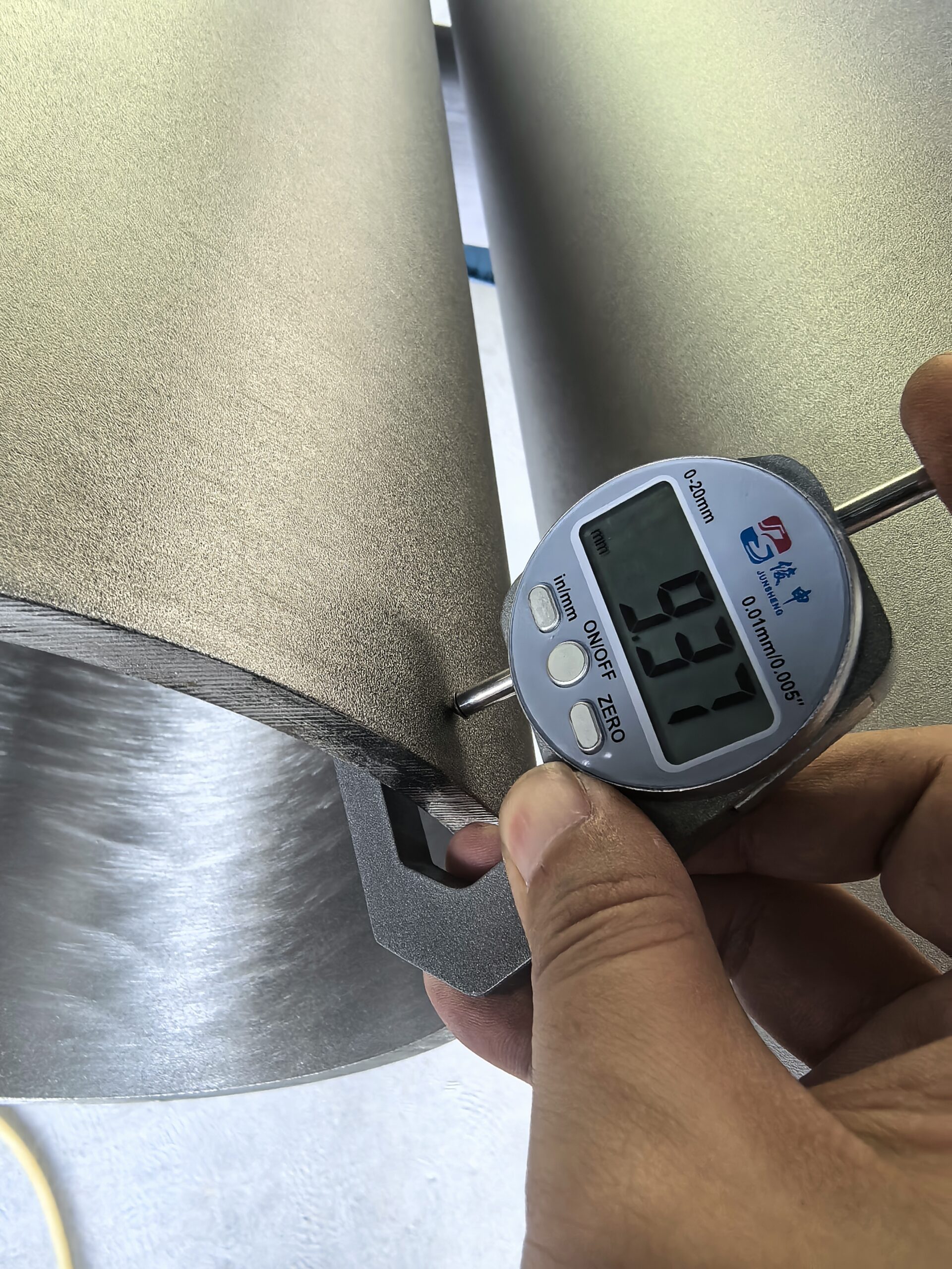
Technician comparing pipe outside diameter and wall thickness with calipers
Pipe size is a system decision, not a single measurement
A pipe does not work alone. It works with pumps, compressors, valves, fittings, insulation, supports, equipment connections, and the layout of the building or process line. Choosing the correct size means looking at the whole system instead of sizing one straight section in isolation.
A larger pipe is not always better. Oversizing can increase material cost, reduce velocity below a useful range, make drainage or cleaning harder, and create fit-up issues in tight spaces. Undersizing can be worse: it may cause pressure drop, higher compressor or pump energy use, unstable flow, water hammer, excessive noise, or equipment starvation.
A practical sizing decision should consider:
- Flow rate: How much fluid, gas, or air must move through the pipe during normal and peak demand.
- Allowable pressure drop: How much pressure the system can lose before performance suffers.
- Pipe material: Steel, copper, PVC, CPVC, PEX, HDPE, stainless steel, aluminum, and other materials have different dimensions and friction behavior.
- Temperatuur: Heat can affect expansion, insulation thickness, pressure rating, and material suitability.
- Fluid properties: Viscosity, density, cleanliness, and corrosiveness all influence sizing.
- Fittings and valves: Elbows, tees, reducers, strainers, and valves add resistance beyond the straight pipe run.
- Future demand: A system expected to expand may need extra capacity, but that should be intentional rather than guessed.
The best pipe size is the one that meets the required flow with acceptable pressure loss, fits the applicable standard, works with available fittings, and remains practical to install and maintain.
Reading a pipe size chart with confidence
A pipe size chart is most helpful when you know what each column means. The common mistake is to focus only on the nominal pipe size and ignore the dimensions that determine real-world compatibility. Before selecting material or ordering components, confirm which measurement the chart is using.
Nominal pipe size
Nominal pipe size is a naming convention. It helps standardize products and fittings, but it does not always equal the actual inside diameter. This is especially important when comparing materials, because plastic tubing, copper tube, steel pipe, and flexible systems may use different sizing conventions.
Outside diameter
Outside diameter is critical for clamps, hangers, holes, grooved couplings, some fittings, and insulation. If a component grips or surrounds the pipe, it usually depends on the outside diameter. A pipe insulation size chart, for instance, often helps match insulation to the pipe’s outside diameter and nominal size.
Inside diameter
Inside diameter is the dimension that most directly affects flow. Even a modest reduction in inside diameter can noticeably increase friction loss in high-flow systems. When using a pipe size calculator, make sure the tool is based on actual inside diameter or the correct schedule, not just the nominal size.
Wall thickness, schedule, or gauge
Wall thickness affects pressure capacity, strength, weight, and inside diameter. Steel pipe may be identified by schedule, while sheet metal or some tubing products may use gauge. A pipe gauge chart can help translate gauge numbers into thickness, but gauge systems vary by material, so avoid assuming one gauge scale applies everywhere.
How do you choose the right pipe size for an application?
Choose the right pipe size by defining the required flow, identifying the allowable pressure drop, selecting the pipe material and standard, accounting for fittings, then checking the actual inside diameter against a pipe sizing chart or pipe size calculator. The goal is not just to make fluid move; it is to move it efficiently, safely, and consistently under real operating conditions.
Start with the demand side of the system. What equipment must be served, and what flow does each point require? Then look at the supply side. A pump, compressor, tank, utility line, or process connection may have its own limits, and the pipe must support the system rather than fight it.
A useful step-by-step sizing process looks like this:
- Define the service. Identify whether the line carries water, compressed air, gas, steam, oil, chemicals, slurry, or another medium.
- Determine peak flow. Size for realistic maximum demand, not only average use.
- Set the acceptable pressure drop. Some applications tolerate more loss than others.
- Choose the material family. Match the pipe material to pressure, temperature, corrosion risk, codes, and installation environment.
- Review pipe size specifications. Confirm nominal size, outside diameter, wall thickness, inside diameter, and pressure rating.
- Account for fittings. Add the resistance from elbows, tees, valves, filters, couplings, and reducers.
- Check velocity. Very high velocity can cause noise, erosion, water hammer, or energy loss; very low velocity may cause settling in some services.
- Confirm compatibility. Make sure fittings, insulation, supports, and equipment connections are available in the selected size.
- Document the selection. Record the standard, material, size, schedule or wall thickness, and any assumptions.
This process helps prevent the two most common errors: choosing pipe from habit and choosing pipe from a chart without understanding the application.
Common charts and calculators used in pipe sizing
Pipe sizing references are valuable, but each one answers a different question. Using the wrong chart can create a false sense of accuracy. A pipe fitting size chart, for example, is not a flow calculation tool; it helps confirm connection compatibility and fitting dimensions.
Pipe dimension chart
A pipe dimension chart is used to verify physical pipe dimensions. It typically supports decisions involving installation clearance, support spacing, insulation selection, fitting compatibility, and weight estimates. Use it early when comparing materials and again before ordering.
Pipe sizing chart
A pipe sizing chart usually connects flow rate, pipe size, velocity, and pressure drop. These charts are often specific to a fluid type or application. A chart for water service should not be treated as a universal chart for steam, compressed air, or viscous liquids.
Compressed air pipe size chart
Compressed air systems need special attention because pressure drop directly affects tool performance and energy use. A compressed air pipe size chart may account for compressor output, line length, pressure, and air demand. Long runs, multiple drops, and undersized headers can make a compressor work harder than necessary.
Pipe fitting size chart
A pipe fitting size chart helps match elbows, tees, unions, reducers, adapters, flanges, and couplings to the pipe. It is especially useful when transitioning between materials or connection styles. Always confirm thread type, pressure rating, gasket compatibility, and joining method, not just nominal size.
Pipe insulation size chart
A pipe insulation size chart helps select insulation that fits properly around the pipe. Insulation sizing depends on pipe outside diameter and insulation thickness. Correct fit matters because gaps, compression, and poorly sealed joints can reduce thermal performance and create condensation problems in cold systems.
Pipe gauge chart
A pipe gauge chart is useful when working with tubing or thin-wall metal products identified by gauge. Remember that gauge numbers are not intuitive: a higher gauge number often means thinner material. Also, gauge thickness may vary by material category, so use the chart that matches the product type.
Pipe size calculator
A pipe size calculator can speed up selection, but it is only as good as the inputs. Flow rate, pipe length, fittings, roughness, pressure, temperature, and fluid properties can all affect the result. Use calculators to refine a decision, not to replace engineering judgment or applicable code requirements.
Application-specific sizing considerations
Different applications put different demands on pipe. A size that works for a short water branch may be wrong for a long compressed air header or a heated process line. The service conditions should shape the sizing method.
Water and general plumbing
Water piping must balance flow, pressure, velocity, and fixture demand. Undersized water lines may cause poor performance when several fixtures operate at once. Oversized lines may increase cost and, in some cases, create longer wait times for hot water delivery because more volume sits in the pipe.
For plumbing applications, local code requirements and approved materials are central. Pipe size specifications should be checked against the intended use, pressure rating, temperature rating, and joining method. If the line serves critical equipment or multiple branches, include the entire developed length and fitting losses in the calculation.
Compressed air
Compressed air is one of the most common places where pipe sizing mistakes become expensive. If the pipe is too small, pressure drops between the compressor and the point of use. Operators may respond by raising compressor pressure, which can increase energy use and still fail to solve poor distribution.
When reviewing a compressed air pipe size chart, pay attention to total line length, peak air demand, operating pressure, and the number of drops. Main headers are often sized larger than branch lines because they carry combined demand. Smooth routing, fewer unnecessary elbows, and properly sized receivers can improve performance along with correct pipe size.
HVAC, hydronic, and chilled water systems
HVAC piping often involves water, glycol mixtures, refrigerant lines, condensate drains, or steam, depending on the system. Sizing affects heat transfer, pump energy, balancing, and noise. Hydronic systems also require attention to velocity and pressure drop so that coils, heat exchangers, and terminal units receive the flow they need.
Insulation is especially important in HVAC. A pipe insulation size chart helps confirm the correct insulation fit, while the insulation thickness should reflect temperature difference, condensation risk, energy goals, and project requirements. Poor insulation selection can undermine an otherwise well-sized system.
Industrial process piping
Industrial piping may involve higher pressures, elevated temperatures, corrosive media, cleaning cycles, or strict material compatibility requirements. In these environments, pipe sizing is tied closely to safety and process reliability. The selected pipe must satisfy flow requirements while matching the correct material standard, wall thickness, rating, and joining method.
For process piping, fittings and valves deserve close review because they may dominate pressure loss in compact layouts. A line with many elbows and control valves may need a different size than a straight run carrying the same flow. Documentation is also more important because maintenance teams need clear information for replacement and troubleshooting.
Fittings, reducers, and transitions change the result
Fittings are not minor details. Every elbow, tee, valve, strainer, union, coupling, and reducer changes how the system behaves. A straight pipe calculation may look acceptable until fitting losses are included.
A pipe fitting size chart helps confirm that parts connect physically, but hydraulic performance requires another layer of review. Sharp turns, sudden reductions, partially open valves, and poorly planned transitions can create turbulence and pressure loss. In some systems, they may also create noise, vibration, or erosion.
Use these practices when fittings are part of the layout:
- Keep routing as direct as practical without sacrificing access or serviceability.
- Avoid unnecessary changes in direction.
- Use gradual transitions when reducing or increasing pipe size.
- Confirm fitting pressure and temperature ratings match the pipe and service.
- Check connection type carefully, especially when adapting between threaded, soldered, welded, grooved, flanged, compression, or solvent-welded systems.
- Include valves, filters, meters, regulators, and specialty components in pressure loss estimates.
The pipe and fitting system should be selected as one package. A correct pipe size paired with restrictive fittings can still perform poorly.
Insulation, clearance, and installation space
Pipe size affects more than flow. Once insulation, supports, labels, valves, access clearance, and movement are included, the installed system may be much larger than the bare pipe. This is especially important above ceilings, in mechanical rooms, inside chases, and around equipment skids.
A pipe insulation size chart can help estimate the final outside dimension after insulation is installed. That dimension influences hanger selection, spacing, penetration sizes, valve access, and the distance needed between adjacent lines. Hot lines may also need room for expansion, while cold lines may need vapor-sealed insulation to manage condensation.
Installation planning should include:
- Bare pipe outside diameter.
- Insulation thickness and finished outside diameter.
- Fitting and valve envelope dimensions.
- Required slope for drainage or venting.
- Expansion, contraction, and movement allowances.
- Access space for maintenance, cleaning, and replacement.
These details can prevent costly field changes. A system that is correctly sized on paper still needs to fit safely and serviceably in the real space.
Mistakes that lead to poor pipe sizing
Many pipe sizing problems begin with assumptions. A team may copy a previous project, match an existing line without checking demand, or select a size based only on connection diameter. Those shortcuts can work in simple cases, but they become risky when flow, distance, pressure, or material changes.
Common mistakes include:
- Using nominal size as actual diameter. This can throw off flow calculations and component selection.
- Ignoring wall thickness. Schedule, gauge, or pressure class can change inside diameter.
- Forgetting fitting losses. A compact system with many fittings may lose more pressure than expected.
- Mixing chart types. A pipe dimension chart and a pipe sizing chart are not interchangeable.
- Overlooking peak demand. Average flow may be much lower than real operating demand.
- Failing to plan for insulation. The installed system may not fit once insulation is added.
- Treating calculators as final authority. A pipe size calculator depends on accurate assumptions and inputs.
- Not checking standards or codes. Some applications require specific materials, ratings, or installation methods.
Avoiding these errors usually costs less than correcting them after installation.
A practical pipe sizing checklist
Before finalizing a pipe size, review the selection from both performance and installation perspectives. This checklist can help organize the decision.
- Confirm the medium being carried and its operating conditions.
- Record normal flow, peak flow, pressure, and temperature.
- Identify the maximum acceptable pressure drop.
- Select the pipe material and applicable standard.
- Check pipe size specifications for actual dimensions.
- Compare the selected size against a reliable pipe sizing chart.
- Use a pipe size calculator when the system has long runs, multiple branches, or sensitive pressure requirements.
- Verify fitting dimensions with a pipe fitting size chart.
- Confirm wall thickness, schedule, or gauge with the correct reference.
- Check insulation fit and finished diameter if thermal protection is needed.
- Include valves, filters, meters, reducers, and equipment connections.
- Make sure the selected size is available, installable, and maintainable.
- Document assumptions so future changes can be evaluated accurately.
This checklist is not a substitute for engineering review where codes, safety, or complex systems are involved. It is a practical way to keep the most important sizing factors visible.
When professional review is worth it
Professional review is worth it when pipe sizing affects safety, production, code compliance, high energy use, or critical equipment performance. It is also wise when a system carries hazardous media, operates at high pressure or temperature, serves many users, or includes long runs with multiple branches. In those cases, the cost of a wrong assumption can be much higher than the cost of proper design.
A qualified designer, engineer, or experienced piping specialist can evaluate pressure loss, material compatibility, expansion, support requirements, and applicable rules. They can also help interpret pipe size specifications when multiple standards or materials are involved. Even if a pipe size chart or calculator gives a quick answer, expert review can catch layout constraints and operating risks that simple tools miss.
Final selection starts with clear requirements
The right pipe size comes from clear requirements, not guesswork. Start with flow, pressure, material, temperature, distance, fittings, and installation conditions, then use the right reference for each decision. A pipe dimension chart confirms physical dimensions, a pipe sizing chart supports flow decisions, a compressed air pipe size chart helps with air distribution, and fitting, insulation, and gauge charts help ensure everything connects and installs correctly.
When in doubt, slow down and verify the assumptions. A well-sized pipe system performs better, uses energy more efficiently, fits the available space, and is easier to maintain over time.
 English
 Afrikaans
 Arabic
 Bengali
 Catalan
 Chinese
 French
 Dutch (Belgium)
 Dutch
Dutch German
 Czech
Czech Greek
Greek Hindi
Hindi Japanese
 Italian
 Portuguese
 Spanish (Chile)
 Spanish (Colombia)
 Spanish (Argentina)
 Persian
 Estonian
 Albanian
 Russian
 Spanish (Peru)
 Indonesian
 Thai
Thai Vietnamese
 Georgian
 Bhojpuri
 Moroccan Arabic
 Korean
 Nepali
 Polish
 Ukrainian
 Malayalam
 Xhosa
Xhosa