 Wenzhou Kaixin Kaixin Metal Co.,LTD

Madhësitë e zakonshme të flanxhave dhe aplikimet e tyre
Flange sizing helps match pipe, valve, pump, and equipment connections so a piping system can be assembled safely and serviced efficiently. The right flange is not chosen by outside diameter alone; it depends on nominal pipe size, pressure class, flange face, bolt pattern, gasket style, material, and the standard used for the system. This guide explains how common flange sizes are used, what to look for in a flange size chart, and how bolt information fits into selection.
Flange types and where they are used
Different flange types solve different installation and service problems. The nominal size may be the same, but the connection method and best application can vary significantly.
Weld neck flanges
Weld neck flanges have a long tapered hub and are butt-welded to the pipe. They are commonly used in higher-pressure, higher-temperature, cyclic, or critical services because the design provides a smooth transition between pipe and flange. The bore is typically matched to the pipe, which helps reduce turbulence and stress concentration.
These flanges are common in tubacioni i procesit, refineries, power plants, chemical systems, and other demanding applications. They require more careful fit-up and welding than some alternatives, but they are often preferred where joint integrity is a priority.
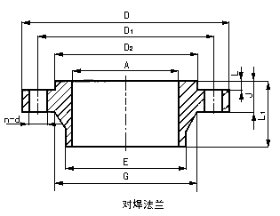
Weld neck flanges Dimension size chart
Slip-on flanges
Slip-on flanges slide over the pipe and are usually welded at the hub and inside edge. They are popular because they are relatively easy to align and install. They are often used in lower-pressure utility and process systems where the service conditions allow them.
Their convenience makes them common in water, air, low-pressure steam, and general plant piping. However, they are not always the best choice for severe cyclic loading or high-integrity service, so project specifications should guide their use.

Slip-on flanges size chart
Socket weld flanges
Socket weld flanges include a recessed area where the pipe is inserted before welding. They are commonly used for smaller-diameter high-pressure piping. The design can simplify alignment, but the internal crevice may be a concern in corrosive or sanitary services.
These flanges are often seen in small-bore process lines, hydraulic systems, and chemical injection connections. They are selected when the benefits of a compact welded joint outweigh the limitations of the socket configuration.
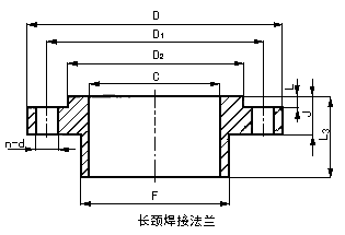
Socket weld flanges drawing of size chart
Threaded flanges
Threaded flanges connect to pipe without welding. This can be useful where hot work is restricted or where small low-pressure connections need to be assembled quickly. They are commonly used in some utility, air, water, and non-severe services.
Threaded connections are generally less suitable for severe vibration, high temperature cycling, or hazardous leakage concerns unless the design specifically allows them. Thread compatibility and sealing method must be verified before installation.

Threaded flanges drawing size chart
Blind flanges
Blind flanges close the end of a pipe, valve, vessel nozzle, or equipment connection. They are used for inspection access, future expansion, pressure testing, and permanent or temporary isolation. Because blind flanges resist pressure without a center bore, they can experience high stress and must match the system rating.
Blind flanges are common across nearly every piping industry. Their bolt pattern must match the mating flange exactly, which makes the flange and bolt Tabela e madhësive especially useful during maintenance work.

Blind Flange Dimension
Stainless Steel Flange Size Chart 1 ANSI 150 RF mm
| OD | ID | Flange | Gjatësi | Lartësia | nut dimension | numbers | Arë | ||||||||||
| Trashësia | Madhësia | ||||||||||||||||
| DN | D | D1 | D2 | A | B | C | E | F | G | J | L1 | L2 | L3 | L | d | n | M |
| 20 | 98 | 70 | 43 | 21 | 28 | 20 | 27 | 38 | 13 | 53 | 16 | 229 | 1.6 | 15 | 4 | 12 | |
| 25 | 108 | 79.5 | 51 | 27 | 35 | 25 | 34 | 51 | 49 | 14 | 56 | 17 | 1.6 | 15 | 4 | 12 | |
| 32 | 118 | 89 | 63.5 | 35 | 43 | 32 | 42 | 60 | 59 | 16 | 57 | 21 | 1.6 | 15 | 4 | 12 | |
| 40 | 127 | 98.5 | 73 | 41 | 50 | 40 | 48 | 67 | 65 | 18 | 62 | 22 | 1.6 | 15 | 4 | 12 | |
| 50 | 152 | 120.5 | 92 | 53 | 62 | 50 | 60.5 | 83 | 78 | 19 | 64 | 25 | 1.6 | 19 | 4 | 16 | |
| 65 | 178 | 139.5 | 105 | 63 | 75 | 65 | 73 | 95 | 91 | 24 | 70 | 29 | 1.6 | 19 | 4 | 16 | |
| 80 | 190 | 152.5 | 127 | 78 | 91 | 80 | 89 | 108 | 108 | 24 | 70 | 30 | 1.6 | 19 | 4 | 16 | |
| 100 | 229 | 190.5 | 157 | 102 | 116 | 100 | 114 | 140 | 135 | 24 | 76 | 33 | 305 | 1.6 | 19 | 8 | 16 |
| 125 | 254 | 216 | 186 | 128 | 144 | 125 | 141 | 165 | 164 | 24 | 89 | 37 | 1.6 | 23 | 8 | M20 | |
| 150 | 279 | 241.5 | 216 | 154 | 171 | 150 | 168 | 197 | 192 | 25 | 89 | 40 | 1.6 | 23 | 8 | M20 | |
| 200 | 343 | 298.5 | 270 | 203 | 221 | 200 | 219 | 248 | 246 | 29 | 102 | 44 | 1.6 | 23 | 8 | M20 | |
| 250 | 406 | 362 | 324 | 255 | 276 | 250 | 273 | 305 | 305 | 30 | 102 | 49 | 1.6 | 25 | 12 | M22 | |
| 300 | 483 | 432 | 381 | 305 | 327 | 300 | 324 | 365 | 365 | 32 | 114 | 56 | 1.6 | 25 | 12 | M22 | |
Stainless Steel Flange Size Chart 2 ANSI 300RF mm
| Madhësia nominale e tubit | OD | Flange | Gjatësi | Lartësia | Bolt Dimension | QTY | Bolt | ||||||||||
| Trashësia | Madhësia | ||||||||||||||||
| DN | D | D1 | D2 | A | B | C | E | F | G | J | L1 | L2 | L3 | L | d | n | M |
| 20 | 117 | 82.5 | 43 | 21 | 28 | 20 | 27 | 48 | 16 | 57 | 25 | 229 | 1.6 | 19 | 4 | 16 | |
| 25 | 124 | 89 | 51 | 27 | 35 | 25 | 34 | 54 | 54 | 17 | 62 | 27 | 1.6 | 19 | 4 | 16 | |
| 32 | 133 | 98.4 | 64 | 35 | 43 | 32 | 42 | 64 | 64 | 19 | 65 | 27 | 1.6 | 19 | 4 | 16 | |
| 40 | 156 | 114.5 | 73 | 41 | 50 | 40 | 48 | 70 | 70 | 21 | 68 | 30 | 1.6 | 23 | 4 | 20 | |
| 50 | 165 | 127 | 92 | 53 | 62 | 50 | 60 | 84 | 84 | 22 | 70 | 33 | 1.6 | 19 | 8 | 16 | |
| 65 | 191 | 149 | 105 | 63 | 75 | 65 | 73 | 100 | 100 | 25 | 76 | 38 | 1.6 | 23 | 8 | 20 | |
| 80 | 210 | 168 | 127 | 78 | 91 | 80 | 89 | 117 | 117 | 29 | 79 | 43 | 1.6 | 23 | 8 | 20 | |
| 100 | 254 | 200 | 157 | 102 | 116 | 100 | 114 | 146 | 146 | 32 | 86 | 48 | 305 | 1.6 | 23 | 8 | 20 |
| 125 | 279 | 235 | 186 | 128 | 144 | 125 | 141 | 178 | 178 | 35 | 98 | 51 | 1.6 | 23 | 8 | 20 | |
| 150 | 318 | 270 | 216 | 154 | 171 | 150 | 168 | 206 | 206 | 37 | 98 | 52 | 1.6 | 23 | 12 | 20 | |
| 200 | 381 | 330 | 270 | 203 | 221 | 200 | 219 | 260 | 260 | 41 | 111 | 62 | 1.6 | 25 | 12 | 22 | |
| 250 | 445 | 387.5 | 324 | 255 | 276 | 250 | 273 | 321 | 321 | 48 | 117 | 67 | 1.6 | 30 | 16 | 27 | |
| 300 | 521 | 451 | 381 | 305 | 327 | 300 | 324 | 375 | 375 | 51 | 130 | 73 | 1.6 | 33 | 16 | 30 | |
Stainless Steel Flange Size Chart 3 ANSI 400RF mm
| Madhësia nominale e tubit | OD | Flange | Gjatësi | Lartësia | Bolt Dimension | QTY | Bolt | ||||||||||
| Trashësia | Madhësia | ||||||||||||||||
| DN | D | D1 | D2 | A | B | C | E | F | G | J | L1 | L2 | L3 | L | d | n | M |
| 20 | 117 | 82.5 | 43 | 按用户要求 | 28 | 20 | 27 | 48 | 22 | 64 | 32 | 235 | 6.4 | 19 | 4 | 16 | |
| 25 | 124 | 89 | 51 | 35 | 25 | 34 | 54 | 54 | 24 | 68 | 33 | 6.4 | 19 | 4 | 16 | ||
| 32 | 133 | 98 | 64 | 43 | 32 | 42 | 64 | 64 | 27 | 73 | 35 | 6.4 | 19 | 4 | 16 | ||
| 40 | 156 | 114 | 73 | 50 | 40 | 48 | 70 | 70 | 29 | 76 | 38 | 6.4 | 23 | 4 | 20 | ||
| 50 | 165 | 127 | 92 | 62 | 50 | 60 | 84 | 84 | 32 | 79 | 43 | 6.4 | 19 | 8 | 16 | ||
| 65 | 191 | 149 | 105 | 75 | 65 | 73 | 100 | 100 | 35 | 86 | 48 | 6.4 | 23 | 8 | 20 | ||
| 80 | 210 | 168 | 127 | 91 | 80 | 89 | 117 | 117 | 38 | 89 | 52 | 6.4 | 23 | 8 | 20 | ||
| 100 | 254 | 200 | 157 | 116 | 100 | 114 | 146 | 146 | 41 | 95 | 57 | 311 | 6.4 | 25 | 8 | 22 | |
| 125 | 279 | 235 | 186 | 144 | 125 | 141 | 178 | 178 | 45 | 108 | 60 | 6.4 | 25 | 8 | 22 | ||
| 150 | 318 | 270 | 216 | 171 | 150 | 168 | 206 | 206 | 48 | 110 | 64 | 6.4 | 25 | 12 | 22 | ||
| 200 | 381 | 330 | 270 | 221 | 200 | 219 | 260 | 260 | 54 | 124 | 75 | 6.4 | 30 | 12 | 27 | ||
| 250 | 445 | 387 | 324 | 276 | 250 | 273 | 321 | 321 | 60 | 130 | 79 | 6.4 | 33 | 16 | 30 | ||
| 300 | 521 | 451 | 381 | 327 | 300 | 324 | 375 | 375 | 64 | 143 | 86 | 6.4 | 35 | 16 | 32 | ||
Stainless Steel Flange Size Chart 4 ANSI 600RF mm
| Madhësia nominale e tubit | OD | Flange | Gjatësi | Lartësia | Bolt Dimension | QTY | Bolt | ||||||||||
| Trashësia | Madhësia | ||||||||||||||||
| DN | D | D1 | D2 | A | B | C | E | F | G | J | L1 | L2 | L3 | L | d | n | M |
| 20 | 117 | 82.5 | 43 | 按用户要求 | 28 | 20 | 27 | 48 | 22 | 64 | 32 | 235 | 6.4 | 19 | 4 | 16 | |
| 25 | 124 | 89 | 51 | 35 | 25 | 34 | 54 | 54 | 24 | 68 | 33 | 6.4 | 19 | 4 | 16 | ||
| 32 | 133 | 98 | 64 | 43 | 32 | 42 | 64 | 64 | 27 | 73 | 35 | 6.4 | 19 | 4 | 16 | ||
| 40 | 156 | 114.5 | 73 | 50 | 40 | 48 | 70 | 70 | 29 | 76 | 38 | 6.4 | 23 | 4 | 20 | ||
| 50 | 165 | 127 | 92 | 62 | 50 | 60 | 84 | 84 | 32 | 79 | 43 | 6.4 | 19 | 8 | 16 | ||
| 65 | 191 | 149 | 105 | 75 | 65 | 73 | 100 | 100 | 35 | 86 | 48 | 6.4 | 23 | 8 | 20 | ||
| 80 | 210 | 168 | 127 | 91 | 80 | 89 | 117 | 117 | 38 | 89 | 52 | 6.4 | 23 | 8 | 20 | ||
| 100 | 273 | 216 | 157 | 116 | 100 | 114 | 152 | 152 | 45 | 108 | 57 | 311 | 6.4 | 25 | 8 | 22 | |
| 125 | 330 | 266.5 | 186 | 144 | 125 | 141 | 191 | 189 | 51 | 121 | 67 | 6.4 | 30 | 8 | 27 | ||
| 150 | 356 | 292 | 216 | 171 | 150 | 168 | 222 | 222 | 54 | 124 | 73 | 6.4 | 33 | 12 | 30 | ||
| 200 | 419 | 349 | 270 | 221 | 200 | 219 | 273 | 273 | 62 | 140 | 83 | 6.4 | 36 | 12 | 33 | ||
| 250 | 508 | 432 | 324 | 276 | 250 | 273 | 343 | 343 | 70 | 159 | 92 | 6.4 | 36 | 16 | 33 | ||
| 300 | 559 | 489 | 381 | 327 | 300 | 324 | 400 | 400 | 73 | 162 | 98 | 6.4 | 36 | 20 | 33 | ||
Stainless Steel Flange Size Chart 5 ANSI 900RF mm
| DN | D | D1 | D2 | A | B | C | E | F | G | J | L1 | L2 | L3 | L | d | n | M |
| 20 | 130 | 89 | 43 | 按用户要求 | 28 | 20 | 27 | 44 | 32 | 76 | 41 | 235 | 6.4 | 23 | 4 | 20 | |
| 25 | 149 | 101.5 | 51 | 35 | 25 | 34 | 52 | 52 | 35 | 79 | 48 | 6.4 | 25 | 4 | 22 | ||
| 32 | 159 | 111 | 64 | 43 | 32 | 42 | 63.5 | 64 | 35 | 79 | 48 | 6.4 | 25 | 4 | 22 | ||
| 40 | 178 | 124 | 73 | 50 | 40 | 48 | 70 | 70 | 38 | 89 | 51 | 6.4 | 30 | 4 | 27 | ||
| 50 | 216 | 165 | 92 | 62 | 50 | 60 | 105 | 105 | 45 | 108 | 64 | 6.4 | 25 | 8 | 22 | ||
| 65 | 244 | 190.5 | 105 | 75 | 65 | 73 | 124 | 124 | 48 | 111 | 70 | 6.4 | 30 | 8 | 27 | ||
| 80 | 241 | 190.5 | 127 | 91 | 80 | 89 | 127 | 127 | 45 | 108 | 60 | 6.4 | 25 | 8 | 22 | ||
| 100 | 292 | 235 | 157 | 116 | 100 | 114 | 159 | 159 | 51 | 121 | 76 | 311 | 6.4 | 33 | 8 | 30 | |
| 125 | 349 | 279.5 | 186 | 144 | 125 | 141 | 190.5 | 191 | 58 | 133 | 86 | 6.4 | 36 | 8 | 33 | ||
| 150 | 381 | 317.5 | 216 | 171 | 150 | 168 | 235 | 235 | 62 | 146 | 92 | 6.4 | 33 | 12 | 30 | ||
| 200 | 470 | 393.5 | 270 | 221 | 200 | 219 | 298 | 298 | 70 | 168 | 108 | 6.4 | 39 | 12 | 36 | ||
| 250 | 546 | 470 | 324 | 276 | 250 | 273 | 368 | 368 | 76 | 191 | 114 | 6.4 | 39 | 16 | 36 | ||
| 300 | 610 | 533.5 | 381 | 327 | 300 | 324 | 419 | 419 | 86 | 206 | 124 | 6.4 | 39 | 20 | 36 |
Stainless Steel Flange Size Chart 6 ANSI 1500RF mm
| Madhësia nominale e tubit | OD | Flange | Gjatësi | Lartësia | Bolt Dimension | QTY | Bolt | ||||||||||
| Trashësia | Madhësia | ||||||||||||||||
| DN | D | D1 | D2 | A | B | C | E | F | G | J | L1 | L2 | L3 | L | d | n | M |
| 20 | 130 | 89 | 43 | 按用户要求 | 28 | 20 | 27 | 44.5 | 32 | 76 | 41 | 235 | 6.4 | 23 | 4 | 20 | |
| 25 | 149 | 101.5 | 51 | 35 | 25 | 34 | 52 | 52 | 35 | 79 | 48 | 6.4 | 25 | 4 | 22 | ||
| 32 | 159 | 111 | 64 | 43 | 32 | 42 | 63.5 | 63.5 | 35 | 79 | 48 | 6.4 | 25 | 4 | 22 | ||
| 40 | 178 | 124 | 73 | 50 | 40 | 48 | 70 | 70 | 39 | 89 | 51 | 6.4 | 30 | 4 | 27 | ||
| 50 | 216 | 165 | 92 | 62 | 50 | 60 | 105 | 105 | 45 | 108 | 64 | 6.4 | 25 | 8 | 22 | ||
| 65 | 244 | 190.5 | 105 | 75 | 65 | 73 | 124 | 124 | 48 | 111 | 70 | 6.4 | 30 | 8 | 27 | ||
| 80 | 267 | 203 | 127 | 91 | 80 | 89 | 133 | 133 | 54 | 124 | 79 | 6.4 | 33 | 8 | 30 | ||
| 100 | 311 | 241.5 | 157 | 116 | 100 | 114 | 162 | 162 | 61 | 130 | 97 | 311 | 6.4 | 35 | 8 | 32 | |
| 125 | 375 | 292 | 186 | 144 | 125 | 141 | 197 | 170 | 80 | 162 | 111 | 6.4 | 42 | 8 | 39 | ||
| 150 | 394 | 317.5 | 216 | 171 | 150 | 168 | 229 | 229 | 89 | 178 | 125 | 6.4 | 45 | 12 | 42 | ||
| 200 | 483 | 393.5 | 270 | 221 | 200 | 219 | 292 | 292 | 99 | 219 | 149 | 6.4 | 45 | 12 | 42 | ||
| 250 | 584 | 482.5 | 324 | 276 | 250 | 273 | 368 | 368 | 115 | 260 | 165 | 311 | 6.4 | 51 | 12 | 48 | |
| ∫ | |||||||||||||||||
| 300 | 673 | 571.5 | 381 | 327 | 300 | 324 | 451 | 451 | 131 | 289 | 187 | 514 | 6.4 | 55 | 16 | 52 | |
Stainless Steel Flange Size Chart 7 ANSI 2500RF mm
| Madhësia nominale e tubit | OD | Flange | Gjatësi | Lartësia | Bolt Dimension | QTY | Bolt | ||||||||||
| Trashësia | Madhësia | ||||||||||||||||
| DN | D | D1 | D2 | A | B | C | E | F | G | J | L1 | L2 | L3 | L | d | n | M |
| 20 | 140 | 98 | 43 | 按用户要求 | 28 | 20 | 27 | 51 | 38 | 86 | 49 | 235 | 6.4 | 23 | 4 | 20 | |
| 25 | 159 | 108 | 51 | 35 | 25 | 34 | 57 | 57 | 41 | 95 | 54 | 6.4 | 25 | 4 | 22 | ||
| 32 | 184 | 130 | 63.5 | 43 | 32 | 42 | 73 | 73 | 45 | 102 | 59 | 311 | 6.4 | 30 | 4 | 27 | |
| 40 | 203 | 146 | 73 | 50 | 40 | 48 | 79 | 79 | 51 | 118 | 67 | 6.4 | 33 | 4 | 30 | ||
| 50 | 235 | 171.5 | 92 | 62 | 50 | 60 | 95 | 95 | 57 | 133 | 76 | 6.4 | 30 | 8 | 27 | ||
| 65 | 267 | 197 | 105 | 75 | 65 | 73 | 114 | 114 | 64 | 149 | 86 | 6.4 | 33 | 8 | 30 | ||
| 80 | 305 | 228.5 | 127 | 91 | 80 | 89 | 133 | 133 | 73 | 175 | 98 | 6.4 | 36 | 8 | 33 | ||
| 100 | 356 | 273 | 157 | 116 | 100 | 114 | 165 | 165 | 83 | 197 | 114 | 6.4 | 42 | 8 | 39 | ||
| 125 | 419 | 324 | 186 | 144 | 125 | 141 | 203 | 203 | 98 | 235 | 137 | 6.4 | 48 | 8 | 45 | ||
| 150 | 483 | 368.5 | 216 | 171 | 150 | 168 | 235 | 235 | 114 | 279 | 159 | 6.4 | 55 | 8 | 52 | ||
| 200 | 552 | 438 | 270 | 221 | 200 | 219 | 305 | 305 | 133 | 324 | 184 | 6.4 | 55 | 12 | 52 | ||
| 250 | 673 | 539.5 | 324 | 276 | 250 | 273 | 375 | 375 | 172 | 426 | 235 | 311 | 6.4 | 67 | 12 | 64 | |
| ∫ | |||||||||||||||||
| 300 | 762 | 619 | 381 | 327 | 300 | 324 | 441 | 441 | 191 | 470 | 260 | 514 | 6.4 | 75 | 12 | 72 | |
What does flange size actually mean?
Flange size usually refers to the nominal tub size, or NPS, that the flange is designed to connect to, not the full outside diameter of the flange. A 4-inch flange, for example, is made for a 4-inch nominal pipe connection, but the flange itself is much larger because it must include a sealing face, bolt holes, and enough metal to handle the rated pressure.
That distinction matters because many flange selection mistakes happen when someone measures the outside edge of an existing flange and assumes that number is the flange size. In practice, the nominal size is confirmed by comparing several measurements against an applicable standard or a reliable flange measurement chart.
Common flange sizing details include:
- Nominal pipe size: The pipe size the flange is intended to connect.
- Pressure class: A rating such as Class 150, 300, 600, 900, 1500, or 2500 in ASME-style systems.
- Bolt circle diameter: The diameter of the circle formed by the centers of the bolt holes.
- Number of bolt holes: Often used with bolt circle and hole diameter to confirm the match.
- Flange outside diameter: Useful for identification, but not enough by itself.
- Face type: Raised face, flat face, ring-type joint, or another sealing configuration.
- Bore or inside diameter: Important for weld neck, slip-on, and socket weld flanges.
When people search for a flange size chart, they are often trying to identify one or more of these values quickly. The safest approach is to treat the chart as a guide for confirmation, not as a substitute for checking the actual standard and service conditions.
Common flange sizes in industrial piping
Flanges are available in a wide range of nominal sizes, from small instrument and utility connections to large process, water, and infrastructure lines. In many industrial settings, common sizes include 1/2 inch, 3/4 inch, 1 inch, 1 1/2 inch, 2 inch, 3 inch, 4 inch, 6 inch, 8 inch, 10 inch, 12 inch, and larger. The most common sizes depend heavily on the industry and the fluid being handled.
Small flanges are often used for drains, vents, sampling connections, compressed air, hydraulic lines, fuel systems, and smaller process branches. Mid-size flanges are common around pumps, strainers, control valves, heat exchangers, and packaged equipment. Larger flanges are more common in water distribution, wastewater treatment, chemical processing, power generation, marine piping, and bulk transfer systems.
A good ansi flange size chart or ASME flange guide normally organizes this information by nominal pipe size and pressure class. That is important because the bolt pattern and flange thickness usually change as pressure class increases, even when the nominal pipe size stays the same.

engineer measuring a pipe flange bolt circle
Pressure class shapes the final selection
Pressure class is one of the most important parts of flange sizing because it affects flange thickness, bolt requirements, gasket load, and overall connection strength. A Class 150 flange and a Class 300 flange may both be made for the same nominal pipe size, but they are not automatically interchangeable. Their dimensions, bolt patterns, and pressure-temperature ratings can differ.
The pressure class does not mean the flange can always operate at that exact pressure under every condition. Actual allowable pressure depends on temperature, material, standard, and service environment. That is why engineering specifications often identify flange standard, class, material grade, gasket type, and bolting requirements together.
In practical terms, pressure class influences:
- Flange thickness: Higher classes generally use heavier flange bodies.
- Bolt size and quantity: Higher classes may require larger bolts, more bolts, or both.
- Gasket choice: Higher-pressure services often require more carefully selected gasket materials and seating stress.
- Equipment compatibility: Valves, pumps, and vessels must match the flange class and facing.
- Installation torque requirements: Bolt tightening must suit the gasket, lubricant, material, and service.
If you are using a flange size and bolt chart, confirm that it matches the pressure class in your specification. A bolt size flange chart for Class 150 should not be used to select bolts for Class 300 unless the chart clearly covers both and separates the data correctly.
How do flange bolt sizes relate to flange size?
Flange bolt sizes are determined by the flange standard, nominal pipe size, pressure class, and facing arrangement. Larger flanges usually need more bolts or larger bolts, but the relationship is not simply linear. The bolt pattern is engineered to create enough gasket compression and resist pressure, pipe loads, vibration, and thermal movement.
A flange bolt size chart typically lists nominal pipe size, pressure class, number of bolts, bolt diameter, bolt length, and sometimes bolt hole diameter. Bolt length may vary depending on whether the connection uses studs, machine bolts, heavy hex nuts, washers, insulating kits, or special gaskets. For this reason, bolt length should be verified against the actual assembly, not chosen from a generic chart alone.
When checking a bolt flange Tabela e madhësive, pay close attention to:
- Bolt diameter: The nominal diameter of the stud or bolt.
- Bolt count: The number of fasteners required around the flange.
- Bolt circle: The centerline circle through the bolt holes.
- Bolt hole diameter: The hole size in the flange, which is larger than the bolt diameter.
- Required length: Affected by flange thickness, gasket thickness, nut height, washers, and projection requirements.
- Thread standard: Must match the specified bolting system and project requirements.
Bolting is not just a fit-up detail. Undersized, mismatched, corroded, or incorrectly tightened bolts can compromise gasket sealing and joint reliability. For critical systems, bolt selection and tightening should follow the applicable engineering procedure.
Measuring an unknown flange in the field
Identifying an existing flange requires more than one measurement. Dirt, corrosion, paint, gasket residue, and old modifications can make field measurements less precise, so it is best to gather several dimensions and compare them to the correct standard.
Use this basic field checklist:
- Measure the flange outside diameter. This gives an initial reference point.
- Measure the inside diameter or bore. Compare it with the connected pipe size.
- Count the bolt holes. Bolt count is one of the fastest identifying clues.
- Measure the bolt hole diameter. Use proper tools and account for wear or corrosion.
- Measure the bolt circle diameter. Measure center to center across opposite holes where possible.
- Check flange thickness. Include whether the flange has a raised face.
- Identify the face type. Flat face, raised face, and ring-type joint connections use different gasket approaches.
- Look for markings. Many flanges are marked with size, class, material, and standard information.
A flange measurement chart can help narrow the answer, especially when markings are missing. Still, final identification should consider the connected pipe, equipment documents, service conditions, and applicable project specifications.
Matching flanges, gaskets, and bolts as a system
A flanged joint works because the flange faces, gasket, and bolts act together. The bolts apply load, the gasket compresses, and the flange faces provide the geometry needed to maintain a seal. If one part is incorrect, the connection can leak even if the nominal flange size appears right.
A practical selection process includes:
- Confirm the standard: ASME, EN, JIS, API, or another standard may apply.
- Confirm nominal size and pressure class: Do not assume based on outside diameter.
- Match the face type: Raised face gaskets do not install the same way as ring-type joint gaskets.
- Choose compatible materials: Consider fluid, temperature, corrosion, and environmental exposure.
- Verify bolt data: Use the correct flange bolt size chart for the standard and class.
- Follow tightening procedures: Proper sequence and torque help distribute gasket load evenly.
For maintenance teams, a combined flange and bolt size chart is useful because it keeps related dimensions together. For engineering teams, the chart is only one part of the design package; calculations, standards, and specifications still control the final selection.
Which flange chart should you use?
Use the flange chart that matches the governing standard, pressure class, nominal pipe size system, and project specification. An ansi flange size chart may be the right starting point for ASME-style piping, but it should not be mixed with metric or international flange systems unless compatibility has been verified.
The term “ANSI flange” is still widely used in industry, even though many current North American flange references are associated with ASME standards. That wording can create confusion when ordering parts or reviewing older drawings. If a document says ANSI, confirm the exact standard, class, facing, and material before purchasing or installing the flange.
A reliable flange size chart should clearly show:
- The standard it follows
- Nominal pipe sizes covered
- Pressure classes included
- Outside diameter
- Flange thickness
- Bolt circle diameter
- Number of bolts
- Bolt hole size
- Raised face or facing notes, when relevant
- Units of measurement
If a chart does not identify its standard or pressure class, treat it as a rough reference only. This is especially important when using online results for terms such as bolt size flange chart, flange bolt size chart, or flange and bolt size chart, because similar-looking charts may apply to different systems.
Common applications by flange size range
Small flanges, such as those used around 1/2 inch through 2 inch nominal pipe sizes, often appear on instrument connections, drains, vents, chemical feed lines, small pumps, and utility branches. They are easy to overlook, but they still require correct gasket and bolt selection.
Medium flanges, often found from 3 inch through 8 inch nominal sizes, are common around plant equipment. Pump suction and discharge lines, strainers, control valves, heat exchangers, and skid-mounted systems frequently use these sizes because they balance flow capacity with manageable installation weight.
Larger flanges, such as 10 inch, 12 inch, and above, are frequently used for high-flow systems. Water mains, wastewater piping, cooling water loops, marine systems, and major process headers may use large flanged connections for access, equipment removal, or isolation. As size increases, handling, alignment, gasket placement, and bolt tightening become more demanding.
Best practices for avoiding flange sizing errors
Flange errors are expensive because they often appear late, when installation crews are ready to assemble the joint. A flange that is the right nominal size but the wrong pressure class, facing, or bolt pattern can stop work immediately.
Use these best practices before ordering or installation:
- Verify the nominal pipe size and pressure class together.
- Check the governing standard instead of relying on visual similarity.
- Compare bolt count, bolt circle, and hole diameter before assuming a match.
- Confirm gasket type and facing compatibility.
- Review material requirements for corrosion, temperature, and fluid compatibility.
- Inspect flange faces for damage before assembly.
- Keep field measurements, drawings, and chart data together for traceability.
- Use qualified procedures for critical bolted joints.
The main takeaway is simple: flange size is a system of related dimensions, not a single measurement. Whether you are using a flange size chart, flange size and bolt chart, or flange measurement chart, the chart should support a broader selection process that includes pressure class, standard, facing, material, gasket, and bolting. When those details line up, the flange connection is far more likely to fit correctly, seal properly, and perform as intended.
 English
 Afrikaans
 Arabic
 Bengali
 Catalan
 Chinese
 French
 Dutch (Belgium)
 Dutch
Dutch German
 Czech
Czech Greek
Greek Hindi
Hindi Japanese
 Italian
 Portuguese
 Spanish (Chile)
 Spanish (Colombia)
 Spanish (Argentina)
 Persian
 Estonian
 Albanian
 Russian
 Spanish (Peru)
 Indonesian
 Thai
Thai Vietnamese
 Georgian
 Bhojpuri
 Moroccan Arabic
 Korean
 Nepali
 Polish
 Ukrainian
 Malayalam
 Xhosa
Xhosa