 Вэньчжоу Кайсинь Кайсинь Металл ЛТД

How to Read a Flange Size Chart
A flange size chart helps you match a flange to a pipe, valve, pump, fitting, or gasket by showing the dimensions that must line up for a safe mechanical connection. The key is not just finding the nominal pipe size, but reading the pressure class, bolt pattern, bolt size, gasket surface, and measurement notes together. This guide explains how to use a flange size chart without confusing similar-looking dimensions.
What does a flange size chart actually show?
A flange size chart is a reference that lists the dimensional details of a flange so you can confirm compatibility before installation, ordering, or inspection. Most charts include nominal pipe size, outside diameter, bolt circle, number of bolt holes, bolt diameter, flange thickness, bore, and sometimes raised face or gasket dimensions. A good flange size and bolt chart lets you check both the flange body and the fastener pattern in one place.
The first thing to understand is that flange charts are not usually organized by the physical pipe outside diameter alone. They are typically grouped by nominal pipe size and pressure class. That means two flanges may both be labeled for the same pipe size, but they can have different thicknesses, bolt quantities, or bolt circle diameters if their pressure classes differ.
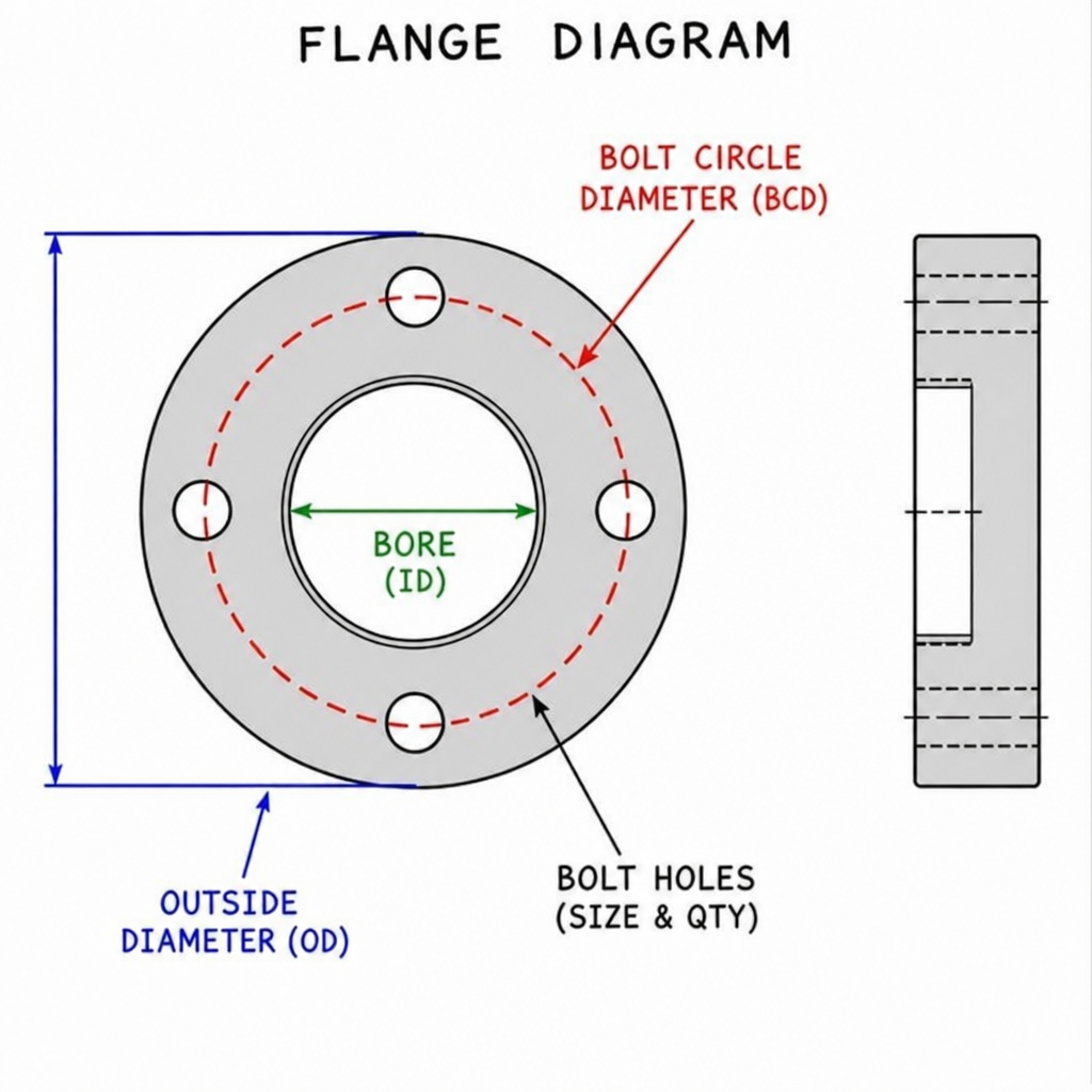
annotated flange diagram showing outside diameter bolt circle bore and bolt holes
The core terms you need before reading the chart
A chart becomes much easier to read when you know what each column is trying to tell you. The exact labels may vary by manufacturer or standard, but the same measurement concepts appear repeatedly.
Nominal pipe size
Nominal pipe size, often abbreviated as NPS, is the trade size of the pipe connection. It is not always the exact measured inside or outside diameter of the pipe. Use it as the starting point, then confirm the other dimensions in the flange measurement chart.
Pressure class
The pressure class identifies the flange rating group, such as common ANSI or ASME-style class designations. Higher classes generally use heavier flange dimensions and may require different bolting. When reading an ansi flange size chart, always choose the correct class before comparing bolt or diameter values.
Outside diameter
Outside diameter is the full width of the flange from edge to edge. This dimension helps confirm the flange body size, but it does not prove that the flange will bolt up correctly. Two flanges can look similar at a glance while having different bolt circle or hole sizes.
Bolt circle diameter
Bolt circle diameter is the diameter of the imaginary circle that passes through the centers of the bolt holes. This is one of the most important values in any flange bolt size chart because it determines whether the bolt holes will align with the mating flange.
Number of bolt holes
The chart will list how many bolts the flange requires. Do not assume that a larger flange always has only a slightly larger version of the same pattern. The number of holes can change by size and class.
Bolt diameter or bolt size
A bolt size flange chart shows the fastener diameter intended for the flange holes. This may appear as bolt diameter, stud bolt size, machine bolt size, or recommended bolt size. Always distinguish between bolt hole diameter and bolt diameter, because the hole is normally larger than the bolt to allow clearance.
A practical step-by-step method for reading the chart
Use a consistent order every time. Jumping straight to bolt size can lead to mistakes if the pipe size or pressure class is wrong.
- Identify the standard or chart family. Confirm whether you are using the right type of chart for the flange specification, application, and region.
- Find the nominal pipe size. Start with the NPS or stated flange size, not a rough tape-measure reading of the flange edge.
- Select the pressure class. Make sure the class column or section matches the system requirement and the mating flange.
- Check the outside diameter. Use this as a quick physical confirmation that you are in the right row.
- Verify the bolt circle. This confirms the spacing of the bolt pattern and prevents alignment problems.
- Count the bolt holes. Compare the chart to the flange in hand, especially when replacing existing parts.
- Confirm bolt size. Use the bolt flange size chart value for the fastener diameter, then verify length and grade separately based on the joint design.
- Review gasket-facing dimensions. If the chart includes raised face or gasket dimensions, confirm they match the gasket and mating flange.
This process works whether the reference is called a flange and bolt size chart, a bolt size flange chart, or a flange measurement chart. The name changes, but the reading sequence stays the same.
Why flange size and bolt details must be read together
A flange is only useful if it can seal and connect correctly with the mating component. The flange body dimensions help establish strength and fit, while the bolt pattern creates the clamping force needed to hold the joint together. If either side of the information is ignored, the connection can be difficult to assemble or unsuitable for service.
For example, using only outside diameter may lead you to choose a flange that appears correct but has the wrong bolt circle. Using only bolt size can be just as misleading, because the same bolt diameter may appear across more than one flange size or class. That is why a combined flange size and bolt chart is more helpful than a fastener-only list.
When checking an existing installation, measure more than one feature. A reliable field check usually includes the flange outside diameter, bolt circle, number of holes, bolt hole diameter, and center bore. These measurements give you enough evidence to match the chart row with more confidence.
Common mistakes when using a flange chart
Even experienced buyers and installers can misread a chart when they are working quickly. Slow down around these common problem areas.
- Confusing nominal size with actual measurement: Номинальный pipe size is a naming system, not always the exact dimension you will measure with a caliper or tape.
- Using the wrong pressure class section: A flange may share the same NPS but not the same thickness, drilling, or bolt requirements.
- Mixing bolt hole diameter and bolt diameter: The chart may list both, and they are not interchangeable.
- Ignoring the mating flange: The flange you select must match the part it connects to, not just the pipe size.
- Assuming all “ANSI” charts are identical: Check the source, standard reference, and any notes before ordering or fabricating.
- Overlooking gasket face details: Raised face, flat face, and other facing details affect gasket selection and joint behavior.
Field measurement checklist before matching a chart
If you are identifying an unknown flange, gather measurements before searching the chart. A flange measurement chart is most useful when your field data is complete.
Measure and record:
- Full outside diameter of the flange
- Inside bore or pipe opening
- Number of bolt holes
- Bolt hole diameter
- Distance across opposite bolt hole centers, when accessible
- Flange thickness
- Raised face diameter and height, if present
- Any markings stamped or cast into the flange
- Pipe size or equipment connection size, if known
Clean the flange face before measuring if corrosion, coating, or gasket residue is present. Use calipers when possible for smaller dimensions, and measure more than once if the flange is worn or damaged. If the flange has no visible markings, the bolt circle and hole count often become the most useful clues.
How to choose the right chart for your job?
Choose the chart that matches the flange standard, pressure class, and application before you compare individual dimensions. A general online flange size chart can be useful for orientation, but purchasing, installation, and inspection decisions should rely on the correct specification and supplier documentation for the exact part.
If you are working with common industrial pipe flanges, an ansi flange size chart may be the reference people ask for, even when the applicable standard is described more specifically in current documentation. In practice, the safest approach is to confirm the chart source, revision, and flange type before making decisions. Manufacturer charts may also include product-specific notes that a simplified reference chart leaves out.
For ordering, do not send only one measurement. Provide the nominal pipe size, class, facing type, material requirement, and bolt pattern details when needed. That gives the supplier enough information to help identify the correct flange instead of guessing from a partial description.
Turning chart data into a confident flange match
Reading a flange chart is a process of elimination. First, narrow the options by nominal pipe size and pressure class. Then confirm the physical dimensions that prove the flange will mate correctly: outside diameter, bolt circle, number of holes, and bolt size. Finally, check the facing and gasket-related details so the joint can be assembled as intended.
The most reliable habit is to treat every chart row as a full set of related dimensions. A bolt size, bore, or outside diameter by itself is only one clue. When you use the full flange and bolt size chart together, you reduce ordering errors, avoid field fit-up problems, and make better decisions before the flange reaches the jobsite.
 English
 Afrikaans
 Arabic
 Bengali
 Catalan
 Chinese
 French
 Dutch (Belgium)
 Dutch
Dutch German
 Czech
Czech Greek
Greek Hindi
Hindi Japanese
 Italian
 Portuguese
 Spanish (Chile)
 Spanish (Colombia)
 Spanish (Argentina)
 Persian
 Estonian
 Albanian
 Russian
 Spanish (Peru)
 Indonesian
 Thai
Thai Vietnamese
 Georgian
 Bhojpuri
 Moroccan Arabic
 Korean
 Nepali
 Polish
 Ukrainian
 Malayalam
 Xhosa
Xhosa